Internal Board Layout
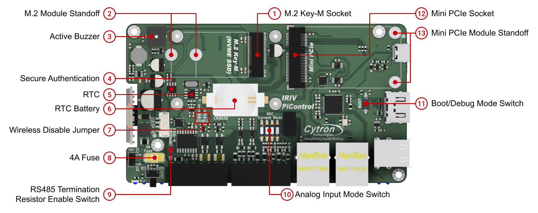
Internal board layout highlighting M.2 Key-M socket, Mini PCIe socket, RTC, secure authentication chip, and configuration switches.
Expansion Sockets
M.2 Key-M Socket
PCIe NVMe SSD support:
- Gen 2 x1-lane PCIe interface
- Supports 2230 and 2242 form factors
- Bootable storage
- M.2 SATA SSD is NOT supported
Installation:
- Use M.2 Module Standoff for mounting 2230 or 2242 modules
- Activity indicated by M.2 LED on front panel
Mini PCIe Socket
Available signals:
- USB 2.0
- SPI
Important limitations:
- PCIe signal is NOT available
- Only USB 2.0 and SPI connections are routed to this socket
- Power to socket controlled via GPIO6 (can be turned on/off programmatically)
Installation:
- Use Mini PCIe Module Standoff for mounting modules
Onboard Devices
Real-Time Clock (RTC)
Chip: PCF85063A Interface: I2C Slave Address 0x51 Battery: CR2032 coin cell socket
- Keeps RTC running when system is powered off
- User-replaceable
Secure Authentication
Chip: ATECC608B Interface: I2C Slave Address 0x60 Function: Crypto authentication for secure applications
Active Buzzer
Control: GPIO19 Behavior: Beeps when GPIO19 output is HIGH Type: User-programmable active piezo buzzer
DIP Switches and Configuration
RS485 Termination Resistor Enable Switch
Function: Connect or disconnect 120Ω termination resistor for RS485 bus Location: Internal board, accessible after opening enclosure Usage: Enable termination at both ends of RS485 bus, disable for intermediate nodes
Analog Input Mode Switch
Function: Configure analog inputs to measure voltage or current Modes:
- Voltage Mode: 0-10V measurement
- Current Mode: 0-20mA measurement
Important: The DIP switch must be set to current mode to enable the internal shunt resistor for 0-20mA measurements.
All four analog input channels share the same mode setting.
Boot/Debug Mode Switch
Function: Select USB-C port operating mode Modes:
- Boot: Flash OS image to CM4 eMMC
- Debug: Access CM4 UART console
Power Protection
4A Fuse
Type: Replaceable fuse Rating: 4 Amp Function: Protects Terminal 1 power input from overcurrent Location: Internal board, accessible after opening enclosure
If the device fails to power up via Terminal 1, check and replace this fuse if necessary.
Wireless Configuration
Wireless Disable Jumper
Function: Disable WiFi or Bluetooth Method: Solder and short the jumper pads to disable wireless functions
Not specified in current sources: Separate jumpers for WiFi vs Bluetooth, or single jumper for both.
I2C Device Summary
| Device | I2C Address | Function |
|---|---|---|
| OLED Display (SSD1306) | 0x3C | System status display |
| ADS1115 ADC | 0x48 | Analog input conversion |
| PCF85063A RTC | 0x51 | Real-time clock |
| ATECC608B | 0x60 | Secure authentication |
Important Notes
NVMe SSD Support
- Fully supported for Gen 2 x1-lane PCIe devices
- Bootable from NVMe SSD
- 2230 and 2242 form factors supported
- SATA M.2 drives are NOT supported
Mini PCIe Limitations
- No PCIe signal available
- Only USB 2.0 and SPI signals connected
- Not suitable for PCIe-based expansion cards
- Suitable for USB-based modules (e.g., 4G/LTE modems with USB interface)
Termination and Mode Switches
- RS485 termination: Enable only at bus endpoints
- Analog mode switch: Applies to all four channels simultaneously
- Current mode requires DIP switch ON to enable shunt resistor
Source(s):
- IRIV PiControl CM4 User Manual, Rev 1.3, Nov 2025, Section 3.2