Interfaces and Mapping
Quick reference for network interfaces, serial device mappings, I2C addresses, and GPIO assignments.
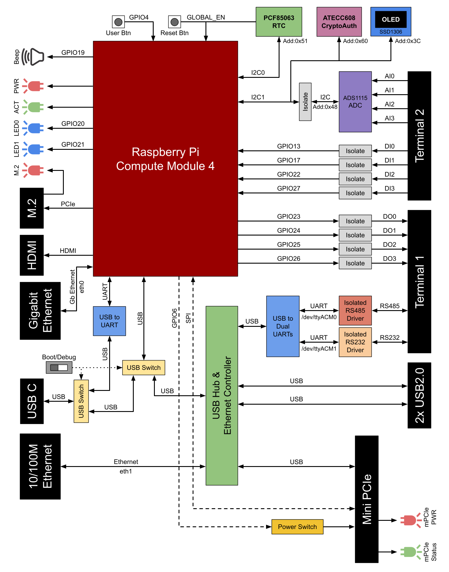
Block diagram showing system architecture, interface connections, and signal flow between CM4, I/O subsystems, and peripheral devices.
Network Interfaces
| Physical Port | Speed | Controller | OS Interface |
|---|---|---|---|
| Gigabit Ethernet | 10/100/1000M | CM4 default Ethernet | eth0 |
| 10/100M Ethernet | 10/100M | USB Ethernet controller | eth1 |
Notes:
- eth0 is the primary CM4 Ethernet interface
- eth1 is extended via USB-to-Ethernet controller
Serial Device Mappings
| Interface | Maximum Baud Rate | Device Path | Notes |
|---|---|---|---|
| RS485 | 500 kbps | /dev/ttyACM0 | Automatic direction control, 120Ω termination available |
| RS232 | 120 kbps | /dev/ttyACM1 | Standard RS232 signals (Tx, Rx, GND) |
Important: Both serial interfaces are accessed via ACM (Abstract Control Model) devices, not traditional TTY serial ports.
I2C Device Addresses
| Device | I2C Bus | Address | Function |
|---|---|---|---|
| SSD1306 OLED | I2C1 | 0x3C | 0.96" status display |
| ADS1115 ADC | I2C1 | 0x48 | 4-channel analog input |
| PCF85063A RTC | I2C0 | 0x51 | Real-time clock |
| ATECC608B | I2C1 | 0x60 | Crypto authentication |
I2C Bus Configuration:
- I2C0 (I2C_vc): Used for RTC on CSI/DSI interface
- I2C1 (I2C_arm): Used for ADC, OLED, and crypto chip
GPIO Mapping
Digital Inputs
| Input | GPIO Pin | Terminal 2 Label |
|---|---|---|
| DI0 | GPIO13 | DI0 |
| DI1 | GPIO17 | DI1 |
| DI2 | GPIO22 | DI2 |
| DI3 | GPIO27 | DI3 |
Characteristics: Wet contact, active HIGH, 3-50V input range
Digital Outputs
| Output | GPIO Pin | Terminal 1 Label |
|---|---|---|
| DO0 | GPIO23 | DO0 |
| DO1 | GPIO24 | DO1 |
| DO2 | GPIO25 | DO2 |
| DO3 | GPIO26 | DO3 |
Characteristics: Dry contact (solid state relay), active HIGH, up to 50V 500mA
User Controls and Indicators
| Function | GPIO Pin | Location |
|---|---|---|
| User Button | GPIO4 | Front panel |
| User LED 0 | GPIO20 | Front panel |
| User LED 1 | GPIO21 | Front panel |
| Active Buzzer | GPIO19 | Internal |
| Mini PCIe Power | GPIO6 | Internal (enable/disable power) |
System Status LEDs
| LED | Function | Control |
|---|---|---|
| PWR (Red) | CM4 power status | Hardware |
| ACT (Green) | CM4 eMMC/storage activity | Hardware |
| M.2 | NVMe SSD activity | Hardware |
Note: PWR and ACT LEDs have the same behavior as the corresponding LEDs on Raspberry Pi 4.
Analog Input Channel Mapping
| Channel | Terminal 2 Label | ADS1115 Input |
|---|---|---|
| AI0 | AI0 | AIN0 |
| AI1 | AI1 | AIN1 |
| AI2 | AI2 | AIN2 |
| AI3 | AI3 | AIN3 |
Common Ground: AGND (isolated from system ground)
USB Interface Mapping
| Port | Type | Speed | Location |
|---|---|---|---|
| USB 2.0 Port 1 | Type-A | 480 Mbps | Right side panel |
| USB 2.0 Port 2 | Type-A | 480 Mbps | Right side panel |
| USB-C | Type-C | Not specified | Right side panel (boot/debug mode) |
Combined current limit for USB 2.0 ports: 1000mA
Expansion Socket Mapping
| Socket | Interface | Signals Available | Notes |
|---|---|---|---|
| M.2 Key-M | PCIe | Gen 2 x1-lane | NVMe SSD only (SATA not supported) |
| Mini PCIe | USB + SPI | USB 2.0, SPI | PCIe signals NOT connected |
Configuration Files
Boot Configuration
File path (Raspberry Pi OS Bullseye and earlier):
/boot/config.txt
File path (Raspberry Pi OS Bookworm and later):
/boot/firmware/config.txt
Background Script
OLED and system monitoring script:
/usr/local/bin/iriv_pi_control/background_script.py
This script runs automatically after configuration to display system status on OLED.
Quick Reference Summary
For GPIO control: See programming-reference.md For terminal wiring: See terminal-1.md and terminal-2.md For hardware locations: See hardware-layout.md and internal-board-layout.md
Source(s):
- IRIV PiControl CM4 User Manual, Rev 1.3, Nov 2025, Sections 3, 4, 5, 6