Hardware Layout
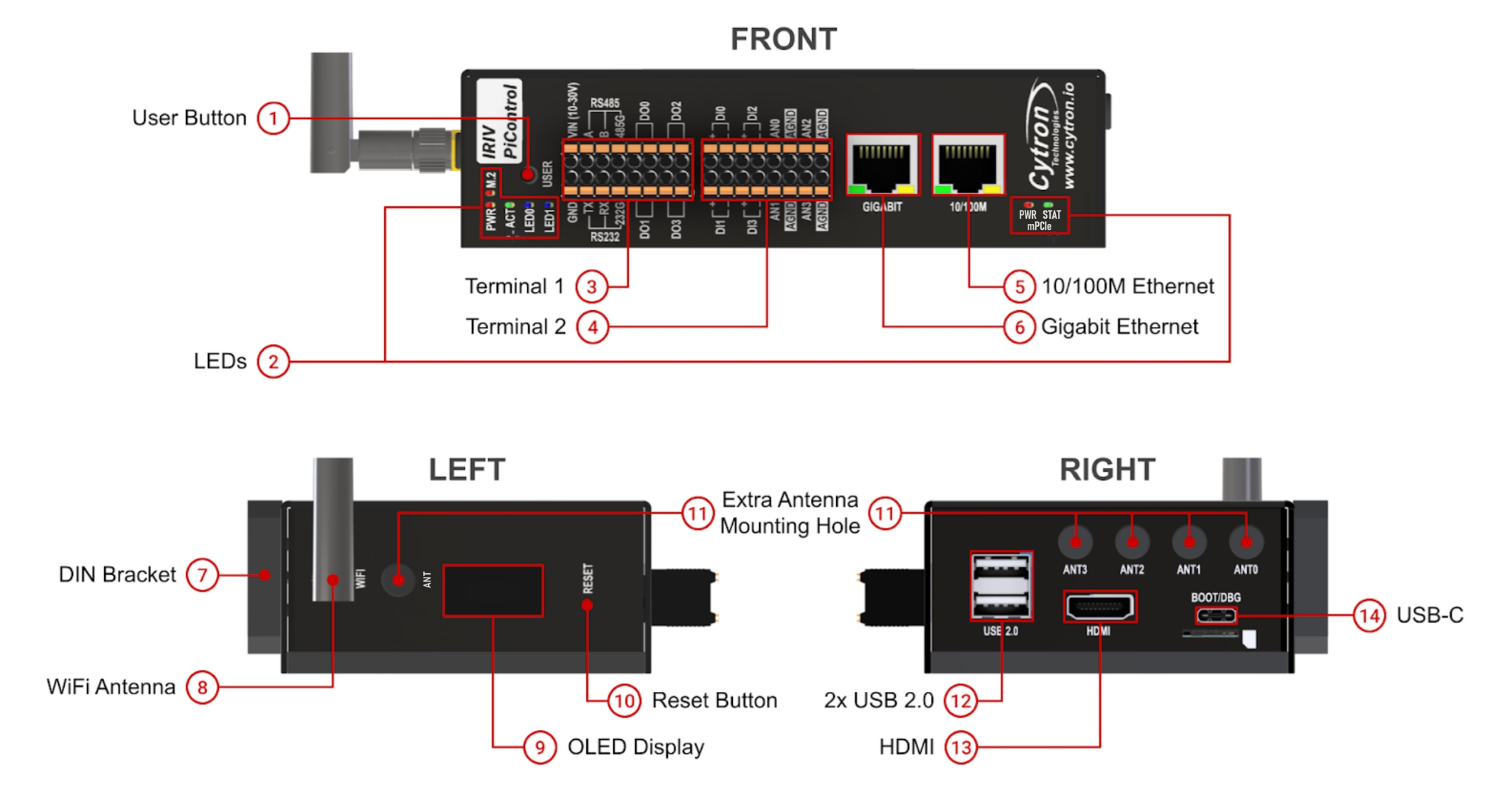
External layout showing all ports, terminals, buttons, LEDs, and connectors on the IRIV PiControl enclosure.
Front Panel
| Component | Description |
|---|---|
| User Button | User-programmable button connected to GPIO4. Can be programmed as a safe shutdown button. |
| LEDs | PWR - CM4 power (red LED, equivalent to Pi 4 red LED) ACT - CM4 activity (green LED, equivalent to Pi 4 green LED) LED0 - User-programmable, controlled by GPIO20 LED1 - User-programmable, controlled by GPIO21 M.2 - NVMe SSD activity indicator |
| Terminal 1 | Pluggable terminal for power, RS485, RS232, digital outputs. See Terminal 1 reference. |
| Terminal 2 | Pluggable terminal for digital inputs and analog inputs. See Terminal 2 reference. |
| 10/100M Ethernet | RJ45 port extended via USB Ethernet controller. Mapped to eth1 in Raspberry Pi OS. |
| Gigabit Ethernet | RJ45 port for default CM4 Ethernet (10/100/1000M). Mapped to eth0 in Raspberry Pi OS. |
Side Panels
Left Side
| Component | Description |
|---|---|
| DIN Bracket | Mounting bracket for DIN rail. Can be repositioned to the bottom of the enclosure. |
| WiFi Antenna (optional) | External antenna for CM4 WiFi and Bluetooth (available on wireless CM4 variants only). |
| Extra Antenna Mounting Hole | Additional mounting holes for antennas. |
| OLED Display | 0.96" SSD1306 OLED display. I2C Slave Address: 0x3C. |
Right Side
| Component | Description |
|---|---|
| Reset Button | Hard reset for Raspberry Pi CM4. Can also wake up CM4 after shutdown. |
| USB 2.0 Ports | 2x USB 2.0 host ports capable of 480Mbps. Maximum combined current: 1000mA. |
| HDMI | Full-size Type-A HDMI port for external display. Supports up to 4K resolution. |
| USB-C | Dual-function port (selectable via internal boot/debug switch): Boot Mode - Load OS image into CM4 eMMC Debug Mode - Access CM4 UART console via USB-UART chip Can also power the IRIV PiControl (5V input). |
Ethernet Port Mapping
| Port | Interface | Speed | OS Mapping |
|---|---|---|---|
| Gigabit Ethernet | CM4 default Ethernet | 10/100/1000M | eth0 |
| 10/100M Ethernet | USB Ethernet controller | 10/100M | eth1 |
USB-C Port Modes
The USB-C port function is selected via the internal Boot/Debug Mode Switch.
Boot Mode
- Used to flash OS images to CM4 eMMC
- Device appears as mass storage when CM4 is in boot mode
- Requires rpiboot utility on host computer
Debug Mode
- Provides serial console access to CM4 UART
- Connected via onboard USB-UART chip
- Console output visible in terminal emulator (115200 baud)
Both modes support 5V power input to the device.
LED Indicators
| LED | Function | Control |
|---|---|---|
| PWR | CM4 power status (red) | Hardware-controlled |
| ACT | CM4 SD/eMMC activity (green) | Hardware-controlled |
| LED0 | User-programmable (blue/white) | GPIO20 |
| LED1 | User-programmable (blue/white) | GPIO21 |
| M.2 | NVMe SSD activity | Hardware-controlled |
Button Functions
| Button | Primary Function | Secondary Function |
|---|---|---|
| User Button | Cycle OLED display pages | Hold 5 seconds: Safe shutdown (when configured) |
| Reset Button | Hard reset CM4 | Wake CM4 after shutdown |
Physical Dimensions
Enclosure only (excluding antenna, DIN socket, and connectors):
- Length: 141.2mm
- Width: 83.5mm
- Height: 39.5mm
For DIN rail mounting dimensions, refer to the user manual Section 7.
Source(s):
- IRIV PiControl CM4 User Manual, Rev 1.3, Nov 2025, Section 3.1