Internal Board Layout
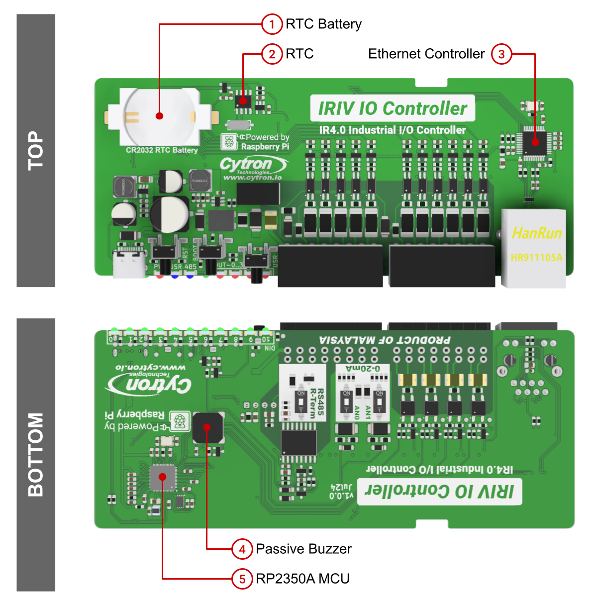
Internal board layout highlighting internal components such as MCU, RTC, Ethernet controller, and onboard devices.
Onboard Components
Raspberry Pi RP2350A Microcontroller
Chip: RP2350A Architecture: Dual ARM Cortex-M33 @ 150MHz RAM: 520KB on-chip SRAM Storage: 2MB flash memory
The RP2350A is the main processing unit that controls all I/O interfaces, communication protocols, and user applications.
Real-Time Clock (RTC)
Chip: PCF85063A Interface: I2C (Slave Address 0x51) I2C Pins: SDA = GPIO16, SCL = GPIO17 Battery: CR2032 coin cell socket
The RTC keeps time running when the system is powered off. Insert a CR2032 coin cell battery to maintain timekeeping during power outages.
Ethernet Controller
Chip: Wiznet W5500 Interface: SPI0 (up to 80MHz) Speed: 10/100M Ethernet SPI Pins:
- INT: GPIO18
- RESET: GPIO23
- CSn: GPIO21
- MOSI: GPIO19
- MISO: GPIO20
- SCK: GPIO22
The W5500 has a built-in TCP/IP stack and supports MODBUS TCP and IT protocols (MQTT/HTTP). It includes 32KB internal memory for TX/RX buffers and supports 8 independent sockets simultaneously.
Passive Buzzer
Control: GPIO11 (PWM capable) Type: Passive buzzer
The passive buzzer can play variable frequency tones or melodies when driven with PWM signals on GPIO11.
Configuration Switches
RS485 Termination Resistor Switch
Location: Bottom of enclosure Function: Enable/disable 120Ω termination resistor for RS485 bus Usage: Turn ON only for the first and last devices in the RS485 chain. Leave OFF for intermediate nodes.
Analog Input Mode Switch
Location: Bottom of enclosure Function: Configure analog inputs to measure voltage or current Modes:
- Voltage Mode: 0-10.56V measurement (input impedance: 32kΩ)
- Current Mode: 0-42.58mA measurement (input impedance: 248Ω)
Note: Both analog input channels (AN0 and AN1) share the same mode setting. The switch configuration applies to both channels simultaneously.
Power Protection
PTC Fuse
Type: Resettable PTC fuse Rating: 500mA Function: Protects Terminal 1 power input from overcurrent and surge events
If the device fails to power up via Terminal 1, the PTC might have opened due to overcurrent. Wait for the PTC to cool down and attempt power-up again. If the issue persists, contact support.
I2C Device Summary
| Device | I2C Address | GPIO Pins | Function |
|---|---|---|---|
| PCF85063A RTC | 0x51 | SDA: GPIO16, SCL: GPIO17 | Real-time clock |
SPI Device Summary
| Device | Interface | GPIO Pins | Function |
|---|---|---|---|
| W5500 Ethernet | SPI0 | MOSI: GPIO19, MISO: GPIO20, SCK: GPIO22, CSn: GPIO21, INT: GPIO18, RESET: GPIO23 | Ethernet MAC/PHY |
Important Notes
W5500 Ethernet Features
- Hardwired TCP/IP protocols: TCP, UDP, ICMP, IPv4, ARP, IGMP, PPPoE
- 8 independent sockets simultaneously
- Power down mode supported
- Wake on LAN over UDP
- Auto-negotiation (full and half duplex, 10 and 100-based)
For detailed W5500 specifications, refer to the Wiznet official website.
RTC Battery
The CR2032 coin cell battery is user-replaceable and maintains RTC operation during power-off periods. The RTC battery socket is accessible after opening the enclosure.
Source(s):
- IRIV IO Controller Datasheet, Rev 1.0, July 2024, Sections 3.2, 5.3