Interfaces and Functions
Technical reference for communication interfaces on the IRIV IO Controller.
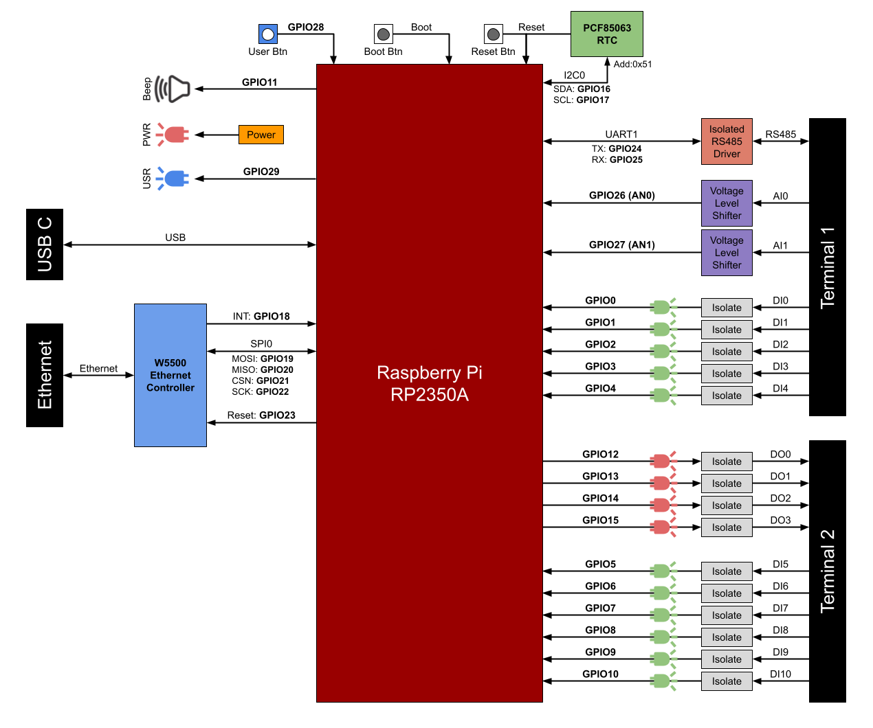
Block diagram providing a high-level overview of system interfaces and signal flow.
RS485 (Isolated)
The IRIV IO Controller provides a fully isolated RS485 interface for industrial serial communication.
RS485 Specifications
| Parameter | Value |
|---|---|
| Maximum Baud Rate | 500 kbps |
| Isolation Voltage | 5000 Vrms |
| Direction Control | Automatic |
| UART Mapping | UART1 (TX: GPIO24, RX: GPIO25) |
| Termination Resistor | 120Ω (switchable via DIP switch) |
RS485 Wiring
The RS485 interface is isolated from the system and other interfaces.
Terminal Connections:
- RS485-A - Differential signal A
- RS485-B - Differential signal B
- RS485-GND - Signal ground
Wiring Recommendations
RS485 typically works by connecting only the A-B differential signals. However, connecting the GND terminal is also recommended for better noise immunity in industrial environments.
Termination Resistor
The RS485 interface includes a 120Ω termination resistor that can be switched on/off via a DIP switch located on the bottom of the enclosure.
Enable termination resistor for:
- First device in RS485 chain
- Last device in RS485 chain
Disable termination resistor for:
- All intermediate devices in RS485 chain
Default Firmware
The IRIV IO Controller ships preprogrammed as a MODBUS RTU IO Expander with counter function. The default firmware communicates via RS485 using the MODBUS RTU protocol.
Ethernet (W5500)
The Ethernet interface is powered by the Wiznet W5500 Ethernet MAC and PHY chip.
Ethernet Specifications
| Parameter | Value |
|---|---|
| Controller | Wiznet W5500 |
| Speed | 10BaseT / 100BaseTX |
| Auto-Negotiation | Full and half duplex, 10 and 100-based |
| Interface to MCU | SPI0 (up to 80MHz) |
| Built-in TCP/IP Stack | Yes |
| Internal Memory | 32KB for TX/RX buffers |
| Maximum Sockets | 8 independent sockets simultaneously |
W5500 SPI Mapping
| Function | GPIO Pin |
|---|---|
| MOSI | GPIO19 |
| MISO | GPIO20 |
| SCK | GPIO22 |
| CSn | GPIO21 |
| INT | GPIO18 |
| RESET | GPIO23 |
Supported Protocols
Hardwired TCP/IP Protocols:
- TCP
- UDP
- ICMP
- IPv4
- ARP
- IGMP
- PPPoE
OT (Operational Technology) Protocols:
- MODBUS TCP
IT (Information Technology) Protocols:
- MQTT
- HTTP/HTTPS
W5500 Features
- 8 independent sockets simultaneously
- Power down mode
- Wake on LAN over UDP
- High-speed SPI interface (MODE 0, 3)
- Internal 32KB memory for TX/RX buffers
- 10BaseT/100BaseTX Ethernet PHY embedded
- Auto-negotiation (full and half duplex, 10 and 100-based)
For detailed W5500 specifications and programming information, refer to the official Wiznet website.
USB-C (Programming and Power)
The USB-C port serves two functions: device programming and power input.
USB-C Specifications
| Parameter | Value |
|---|---|
| Function | Programming and configuration |
| Power Input Voltage | 4.9V to 5.2V DC |
| Programming Method | RP2350A bootloader (UF2 files) |
Programming Mode
To enter programming mode:
- Press and hold the Boot button (pinhole button)
- While holding Boot, press the Reset button (pinhole button)
- Release both buttons
- Device appears as a mass storage drive on the computer
- Drag and drop UF2 firmware files to the drive
- Device automatically reboots after upload completes
Power Input
The USB-C port can power the entire IRIV IO Controller at 5V. The acceptable voltage range is 4.9V to 5.2V DC.
Note: Power consumption is specified at maximum 0.7W according to the datasheet.
Additional Programmable Functions
User Button
- GPIO: GPIO28
- Type: Active low (triggered when pressed)
- Access: Pinhole button, requires paperclip
User programmable button for custom applications.
User LED
- GPIO: GPIO29
- Control: Direct GPIO control
User programmable LED indicator for custom status display.
Passive Buzzer
- GPIO: GPIO11
- Type: PWM-capable
- Function: Variable frequency tone or melody generation
The passive buzzer requires PWM signal to generate audible tones. It can play variable frequencies for alerts, notifications, or melody playback.
Real-Time Clock (RTC)
- Chip: PCF85063A
- Interface: I2C (Slave Address 0x51)
- I2C Pins: SDA = GPIO16, SCL = GPIO17
- Battery: CR2032 coin cell (user-replaceable)
The RTC maintains accurate timekeeping when the system is powered off. Insert a CR2032 battery to enable time retention during power outages.
Source(s):
- IRIV IO Controller Datasheet, Rev 1.0, July 2024, Sections 5.2, 5.3