Hardware Layout
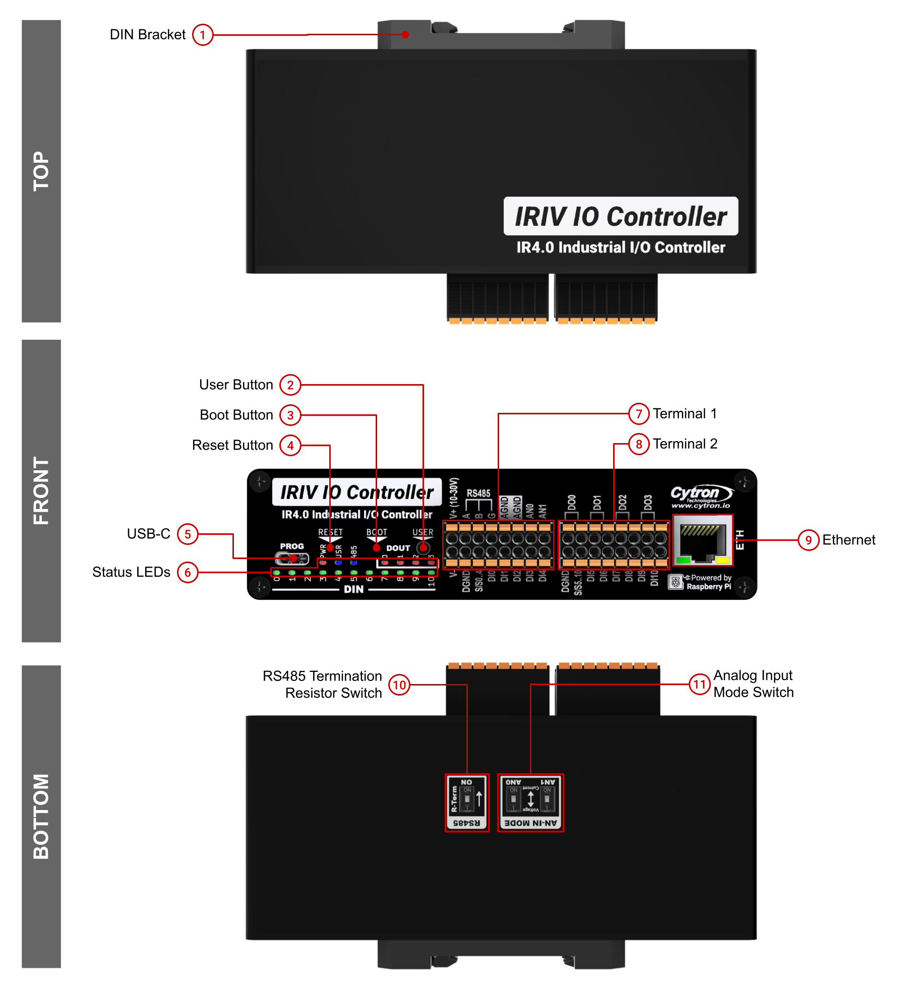
External layout showing all buttons, terminals, LEDs, and connectors on the IRIV IO Controller enclosure.
Front Panel
| Component | Description |
|---|---|
| User Button | User programmable button connected to GPIO28 (active low). Accessible via pinhole, requires paperclip. |
| Boot Button | Press and hold while resetting to enter bootloader mode for programming. Pinhole button, requires paperclip. |
| Reset Button | Press to reset the RP2350A microcontroller. Pinhole button, requires paperclip. |
| Status LEDs | PWR - Power indicator, turns on when device is powered USR - User programmable LED, controlled by GPIO29 485 - RS485 activity indicator DOUT 0-3 - Turn on when corresponding digital output is activated DIN 0-10 - Turn on when corresponding digital input is triggered |
| USB-C | Used for programming and can also power the device (5V input). |
| Terminal 1 | Pluggable terminal for power input, RS485, and analog inputs. See Terminal 1 details below. |
| Terminal 2 | Pluggable terminal for digital inputs and digital outputs. See Terminal 2 details below. |
| Ethernet | RJ45 Ethernet port driven by Wiznet W5500 Ethernet controller (10/100M). |
Bottom Panel
| Component | Description |
|---|---|
| DIN Bracket | Mounting bracket for DIN rail installation. |
| RS485 Termination Resistor Switch | DIP switch to enable/disable the 120Ω termination resistor. Enable only for first and last devices in RS485 chain. |
| Analog Input Mode Switch | DIP switch to configure analog inputs for voltage mode (0-10V) or current mode (0-40mA). |
Terminal 1
Terminal 1 provides power input, RS485 communication, and analog inputs.
| Pin Label | Function |
|---|---|
| V+ | Power supply positive (10-30V DC) |
| DGND | Digital ground for power supply |
| S/S | RS485 Sink/Source |
| A | RS485 A signal |
| B | RS485 B signal |
| AGND | Analog ground (shared with system GND) |
| AN0 | Analog input 0 (GPIO26) |
| AN1 | Analog input 1 (GPIO27) |
Terminal 2
Terminal 2 provides digital inputs and digital outputs in two groups.
DIN Group 1 (DI0-DI4)
| Pin Label | Function |
|---|---|
| DGND | Digital ground for dry contact inputs |
| S/S0..4 | Common sink/source for DIN Group 1 |
| DI0 | Digital Input 0 (GPIO0) |
| DI1 | Digital Input 1 (GPIO1) |
| DI2 | Digital Input 2 (GPIO2) |
| DI3 | Digital Input 3 (GPIO3) |
| DI4 | Digital Input 4 (GPIO4) |
DIN Group 2 (DI5-DI10) and DOUT (DO0-DO3)
| Pin Label | Function |
|---|---|
| DGND | Digital ground (shared between groups) |
| S/S5..10 | Common sink/source for DIN Group 2 |
| DI5 | Digital Input 5 (GPIO5) |
| DI6 | Digital Input 6 (GPIO6) |
| DI7 | Digital Input 7 (GPIO7) |
| DI8 | Digital Input 8 (GPIO8) |
| DI9 | Digital Input 9 (GPIO9) |
| DI10 | Digital Input 10 (GPIO10) |
| DO0 | Digital Output 0 (GPIO12) |
| DO1 | Digital Output 1 (GPIO13) |
| DO2 | Digital Output 2 (GPIO14) |
| DO3 | Digital Output 3 (GPIO15) |
Button Functions
| Button | Function | Access Method |
|---|---|---|
| User Button | User programmable (GPIO28, active low) | Pinhole button, requires paperclip |
| Boot Button | Enter bootloader mode when held during reset | Pinhole button, requires paperclip |
| Reset Button | Reset the RP2350A microcontroller | Pinhole button, requires paperclip |
LED Indicators
| LED | Function | Control |
|---|---|---|
| PWR | Power status | Hardware-controlled |
| USR | User programmable | GPIO29 |
| 485 | RS485 activity indicator | Hardware-controlled |
| DOUT 0-3 | Digital output status (4 LEDs) | Follows digital output state |
| DIN 0-10 | Digital input status (11 LEDs) | Follows digital input state |
Physical Dimensions
Metal enclosure only (excluding DIN socket and connectors):
- Length: 140mm
- Width: 60mm
- Height: 36mm
The DIN bracket allows mounting on standard 35mm DIN rail.
Source(s):
- IRIV IO Controller Datasheet, Rev 1.0, July 2024, Section 3.1